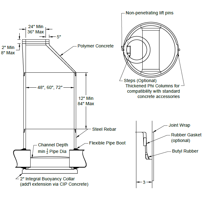
 48–72 IN.
01 / ISSUED STANDARD DRAWING
Cone-top standard detail
Standard cone, riser, base, channel, lifting-point and joint arrangement for 48, 60 and 72 inch inside diameters.
 P3 POLYMERS
ENGINEERS / DRAWINGS + DOWNLOADS
Standard geometry, controlled specification files and field-component literature—organized around the decision in front of the project team.
01 / STANDARD DETAILS
Cone-top structures form the standard 48–72 inch range. Flat lids are available across the range and become the standard platform for larger diameters. Approved project shop drawings still govern openings, reinforcing and component arrangement.
48–72 IN.Standard cone, riser, base, channel, lifting-point and joint arrangement for 48, 60 and 72 inch inside diameters.
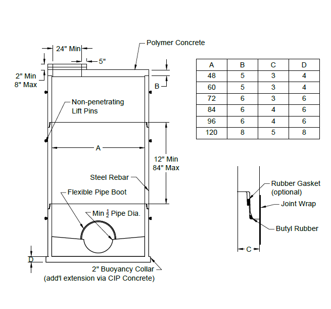 48–120 IN.
Standard flat-lid arrangement and key dimensions for 48 through 120 inch inside diameters, including the large-size platform.
Use note. These standard drawings support planning and coordination; they are not project shop drawings. Do not scale them. Confirm the issued project submittal before construction.
02 / DOCUMENT LIBRARY
Open documents in a new tab for review or download the source file. Project specifications, approved submittals and the latest issued manufacturer instructions control.
Editable Section 33 05 61 contract language for circular precast polymer concrete manholes.
Clause-level engineering rationale, coordination notes and references for the companion specification.
Current certificate for P3 Polymers' quality management system, covering structural polymer fabrication and machining.
Inspection, unloading, rigging, foundation, assembly, connections, backfill and field coordination.
Embedded lift-pin composition and 4,000 lb working-load reference for lift planning.
ASTM C923 connector selection by actual pipe outside diameter, opening and torque guidance.
Connector ranges for large pipe, including required opening and minimum structure size.
Pre-lubricated gasket selection, identification, pressure rating and installation sequence.
Manufacturer product data for the project-specified butyl joint-sealing system.
Exterior joint-wrap properties, preparation, application and overlap guidance.
External rubber joint wrap with cleaning, overlap and full-circumference application guidance.
Primer and heat-shrink sleeve system for chimney and barrel joints.
03 / PROJECT SUBMITTAL
A complete submittal connects the published product platform to actual geometry, loading, interfaces and installation conditions.
DOCUMENT CONTROL
Third-party component literature supports selection and installation of the named accessory; it does not replace the project specification, approved shop drawings, sealed design or P3 installation requirements.
Open the contractor field workflow →