 P3 POLYMERS
MANHOLES + WET WELLS / NEW STRUCTURES
Polymer concrete, from top to invert.
A reinforced structural system configured for gravity-flow manholes or pumping wet wells—with corrosion resistance carried through the wall, base, risers and top components.
01 / MANHOLES + WET WELLS
One structural system, configured around the service.
Manholes and wet wells use the same reinforced polymer concrete structure, joints and pipe connections. Manholes are arranged around gravity flow. Wet wells are configured around pumps, operating levels, access and equipment openings.
- Standard inside diameters
- 48–120 in
- Material
- Polymer concrete throughout
- Standard limited warranty
- 50 years
02 / STANDARD DETAILS
View the standard details.
Select a configuration to review typical geometry, component dimensions and pipe-opening limits. Project drawings confirm the final arrangement.
Cone-top structures
48 / 60 / 72" nominal inside diameter
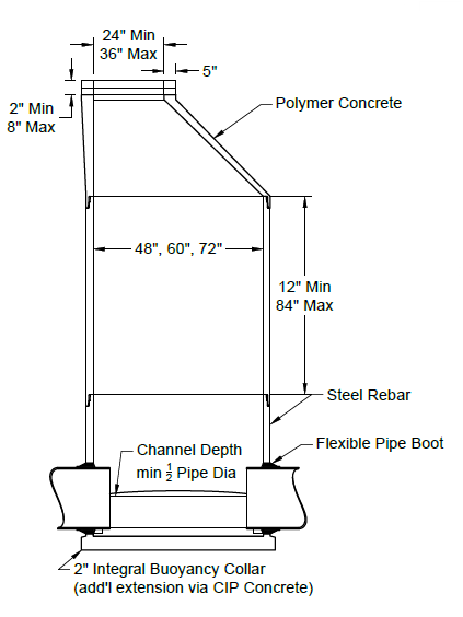
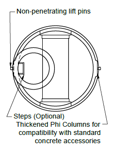
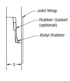
Key dimensions and pipe-opening limits.
Pipe limits use actual outside diameter, not nominal pipe size.
STANDARD BASEMAX PIPE OD
EYEBROW BASE
The drawings show standard component dimensions. Pipe layout, elevations, loads and final reinforcing are confirmed for each project.
Discuss a project →03 / MANHOLE PARTS
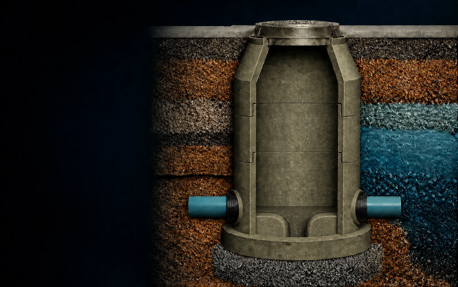
Every part has a job.
Select a numbered marker to see how each part works and the standard behind it.
04 / INSTALLATION
Different material. Familiar installation.
The pieces arrive ready to set. Installation follows the familiar precast sequence: prepare the base, lift each piece, seal the joints, connect the pipes and backfill.
01BEFORE SETTING THE BASE Prepare a level, fully supported base.
Control groundwater and confirm stable bedding before setting the first piece.
CHECKThe ground and bedding are stable, level and ready for the base.02BEFORE LIFTING Use the marked lifting points.
Use rated rigging and set each piece in order. Do not lift or support a piece by a joint or pipe opening.
CHECKThe lifting points, rigging and setting order are confirmed.03AT EVERY JOINT Clean, seal and fully seat.
Clean the shiplap, install the specified gasket or sealant and check alignment.
CHECKThe joint is fully and evenly seated all the way around.04BEFORE BACKFILLING Connect the pipes and protect the joints.
Support and align each pipe so it does not bear on the connector, then backfill evenly.
CHECKThe pipes are aligned and backfill can proceed without moving the manhole.
A familiar precast sequence with no field-applied corrosion lining.
If the project needs extra weight or anchoring against flotation, it is determined before installation.
See installation guidance →05 / PROJECT FIT
Start with the structure and the conditions.
Share the plans, dimensions, exposure, loading, groundwater or condition information you have. P3 can help determine which product path fits while project design remains with the project engineer.